YUASA(汤浅)蓄电池,GS蓄电池,GS YUASA蓄电池
本文讨论了备用电源应用中 (YUASA)VRLA AGM 和 汤浅 VRLA GEL 电池在使用具有恒压特性和有限电流输出的市售电池充电系统充电时的浮动电压特性。
待机应用中的电池需要足够高的充电电压以在放电后重新充电,并保持完全充电状态而不会对电池过度充电。该电压需要针对不同的工作温度进行调节,但为简单起见,本文档考虑在 20oC 下工作。本文档中显示的原理和总体特性可被视为适用于 0oC 和 40oC 之间的工作温度。
施加到电池端子的电压将导致电流流动,这将导致在单个电池或单体电池上看到不同的电压。因此,除了施加到电池端子的浮动电压外,还有更多内容需要讨论。如果所有备用电池的标称电压均为 2V,即所有电池并联,则主题和特性将很简单。然而,我们生活在现实世界中,2V 电池通常串联连接,导致电池电压从通常为 24V 或 48V 的电信系统到高达 1000V 的 UPS 应用。
当在 20oC 下运行时,YUASA(汤浅)AGM 产品通常需要大约 2.27Vpc 至 2.29Vpc 的浮动电压,而 GEL 产品通常在 2.23Vpc 至 2.25Vpc 之间浮动充电。这主要是由于电解液的比重不同。尽管值不同,但两种类型对施加电压的总体反应相似。在电池串联连接形成电池的情况下(如上所述),施加的电压将是每个电池所需的电压乘以电池中的电池数量 (Vpc xn)。施加到电池端子的电压将导致电流流过所有电池或单体电池。在稳态充满电的条件下,该电流非常低,电池串中每个电池(或单体)的电压总和将是充电器施加的总电池电压。尽管由于施加的电压而流过的电流在所有电池中都是相同的,但由于制造差异,每个电池或单体电池上的电压将不同。当电池处于充满电的稳定状态时,差异很小,但仍然很明显,可能会导致对电池状况的误解。已经表明,不能依赖单个电压的“快照”来测量充电状态。可能只有一个例外,即在正常充满电的浮动模式下,个别电压非常低且小于约 2.10V 时。尽管由于施加的电压而流过的电流在所有电池中都是相同的,但由于制造差异,每个电池或单体电池上的电压将不同。当电池处于充满电的稳定状态时,差异很小,但仍然很明显,可能会导致对电池状况的误解。已经表明,不能依赖单个电压的“快照”来测量充电状态。可能只有一个例外,即在正常充满电的浮动模式下,个别电压非常低且小于约 2.10V 时。尽管由于施加的电压而流过的电流在所有电池中都是相同的,但由于制造差异,每个电池或单体电池上的电压将不同。当电池处于充满电的稳定状态时,差异很小,但仍然很明显,可能会导致对电池状况的误解。已经表明,不能依赖单个电压的“快照”来测量充电状态。可能只有一个例外,即在正常充满电的浮动模式下,个别电压非常低且小于约 2.10V 时。当电池处于充满电的稳定状态时,差异很小,但仍然很明显,可能会导致对电池状况的误解。已经表明,不能依赖单个电压的“快照”来测量充电状态。可能只有一个例外,即在正常充满电的浮动模式下,个别电压非常低且小于约 2.10V 时。当电池处于充满电的稳定状态时,差异很小,但仍然很明显,可能会导致对电池状况的误解。已经表明,不能依赖单个电压的“快照”来测量充电状态。可能只有一个例外,即在正常充满电的浮动模式下,个别电压非常低且小于约 2.10V 时。
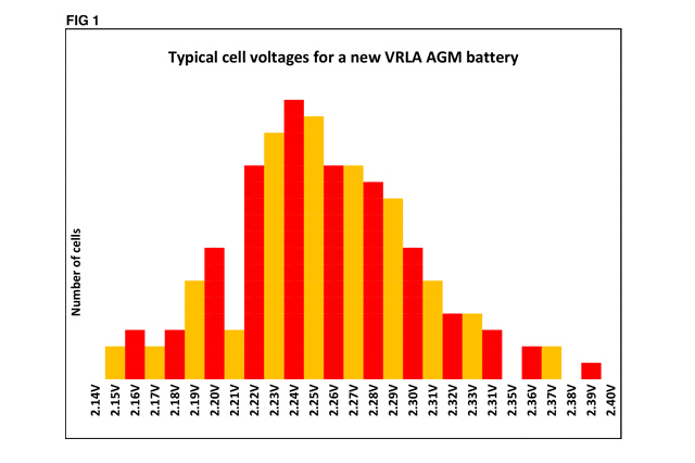
当电池首次在现场充电并施加 2.28Vpc xn 的电压(典型的 AGM 电池)时,通常会测量到低至 2.12Vpc 和高达 2.41Vpc 的个别电压。这证明了两件事:a) 由于制造公差,单个电池存在微小差异,b) 它们将处于不同的充电状态。电池制造商推荐的调试充电将有助于在电池上线之前稳定各个电压。尽管如此,可能需要数周时间才能使整个电池串中的各个电压达到合理一致的值。通常情况下,连续浮充 3 个月后单个电池电压的变化将优于 ±0.07Vpc。即在这个例子中大约在 2.21Vpc 和 2.34Vpc 之间,取决于施加在电池端子上的实际浮动电压。参见下面的图 1,它说明了新 VRLA AGM 电池的单个电池的浮动电压分布
建立稳定的完全充电状态后,电压测量可用于识别可疑的低电量电池。例如,如果大多数电池的电压在 2.21V 和 2.34V 之间,只有少数电池的电压超出此范围,则应进行额外的监测以确定这些较低的电池是否恢复或继续下降浮动电压。当电池电压在此范围内时,除了按照电池制造商的建议定期监测和记录浮充电压外,无需采取任何特殊措施。对于单块电池,可以使用相当于电池数量分别乘以 2.21V 和 2.34V 的电压,前提是要进行非常密切的监控。在多电池单体中识别低容量电池更加困难。一段时间内浮动电压的比较将显示该集团是否具有低容量电池。因此,随着时间的推移,记录应该被保存和比较。
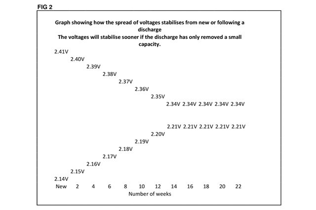
多次表明,放电后,即使幅度极低,电压稳定性也会受到破坏,浮动电压的分布也会增加。这些会稳定下来,但可能需要数周时间,具体取决于放电深度。请参见下面的图 2,它说明了可以预期的变化以及这些变化如何随着时间的推移而缩小。图 2 中的值代表同一电池内单个电池的最高值和最低值。
我们知道 AGM 在 20oC 时的正常充电电压通常在 2.27Vpc 和 2.29Vpc 之间,对于 GEL 产品在 2.23Vpc 和 2.25Vpc 之间,我们可能希望以更高的电压电平充电以减少充电时间。对于 AGM 产品,许多制造商引用 2.40Vpc 的电压,而 GEL 产品引用 2.45Vpc。在使用这些升高的电压之前,必须了解并考虑更高的充电电流会产生更多的热量和气体,并且可能需要额外的通风。使用这些更高电压的好处不仅仅是缩短充电时间。使用上述更高的电压将导致充满电的电流比使用正常浮动电压高约 10 倍。这对调试充电和放电后的再充电都有好处,因为它有助于更快、更有效地转化放电的活性材料。更高的电压也会导致更好的稳定电压,并且当电池恢复到正常浮动电压时电压分布不会那么高。使用这些更高的电压时提供足够的通风非常重要,并且电池必须在充电完成后恢复到正常的浮充电压;否则可能会大大缩短电池寿命。许多工程师建议每年以高于正常浮动水平的水平充电,以帮助稳定电池。对总电池寿命的影响很小。理论上,以 2.40Vpc 充电 24 小时可能会使寿命缩短约 1 周。
在考虑对 VRLA 电池进行浮充或充电时,仅查看电压是不够的。我们还应该考虑充电源的电流能力和特性。大多数制造商建议电池可用的电流应至少为电池 10 小时安培小时的 5%,即 5% C10A。一些制造商推荐 10%,而其他制造商可能推荐 3%。如果没有足够的电流,电池可能永远不会充电,但可能会保持平衡状态。下次放电时将发生故障。曾出现过因太阳能电池板不足而给大容量电池充电,不到一年电池就被毁坏的情况。在一个示例中,一个 5000Ah 的电池有一个 50A (1%) 的太阳能电池板。失败后,该系统经过重新设计,使用具有受控充电机制的较小容量电池,该机制能够将电压提升至典型值 2.40Vpc,并在预编程时间段后使电池恢复浮充电,电流能力至少为 10%C10A。作为额外的预防措施,安装了柴油发电机和单独的充电器,每年使用升高的电压为系统完全充电和重新调试。几年后,整个电池系统继续成功运行。安装了柴油发电机和单独的充电器,每年使用升高的电压为系统完全充电和重新调试。几年后,整个电池系统继续成功运行。安装了柴油发电机和单独的充电器,每年使用升高的电压为系统完全充电和重新调试。几年后,整个电池系统继续成功运行。
虽然电压纹波会对电池寿命产生严重影响,但现代充电设备可以轻松满足电池制造商的要求,因此本文不予讨论。
YUASA battery, GS battery, GS YUASA battery
This paper discusses the floating voltage characteristics of VRLA AGM and Tangshen VRLA GEL batteries in the application of standby power supply (YUASA) when using the commercial battery charging system with constant voltage characteristics and limited current output.
The battery in the standby application needs high enough charging voltage to recharge after discharge and maintain the fully charged state without overcharging the battery. This voltage needs to be adjusted for different operating temperatures, but for simplicity, this document considers working at 20oC. The principles and general characteristics shown in this document can be considered suitable for operating temperatures between 0oC and 40oC.
The voltage applied to the battery terminals will cause the current to flow, which will cause different voltages to be seen on individual cells or individual cells. Therefore, in addition to the floating voltage applied to the battery terminals, there is more to be discussed. If the nominal voltage of all standby batteries is 2V, that is, all batteries are connected in parallel, the theme and characteristics will be very simple. However, we live in the real world, where 2V batteries are usually connected in series, resulting in the battery voltage ranging from 24V or 48V telecom systems to 1000V UPS applications.
When operating at 20oC, YUASA AGM products usually need a floating voltage of about 2.27Vpc to 2.29Vpc, while GEL products usually float between 2.23Vpc and 2.25Vpc. This is mainly due to the different specific gravity of the electrolyte. Although the values are different, the overall response of the two types to the applied voltage is similar. In the case where the batteries are connected in series to form a battery (as described above), the applied voltage will be the voltage required for each battery multiplied by the number of cells in the battery (Vpc xn). The voltage applied to the battery terminals will cause the current to flow through all cells or single cells. Under the condition of full charge in steady state, the current is very low. The total voltage of each battery (or monomer) in the battery string will be the total battery voltage applied by the charger. Although the current flowing due to the applied voltage is the same in all cells, the voltage on each cell or single cell will be different due to manufacturing differences. When the battery is in a stable state of full charge, the difference is small, but it is still obvious, which may lead to misunderstanding of the battery condition. It has been shown that the state of charge cannot be measured by relying on a "snapshot" of a single voltage. There may be only one exception, that is, in the floating mode of normal full charge, when the individual voltage is very low and less than about 2.10V. Although the current flowing due to the applied voltage is the same in all cells, the voltage on each cell or single cell will be different due to manufacturing differences. When the battery is in a stable state of full charge, the difference is small, but it is still obvious, which may lead to misunderstanding of the battery condition. It has been shown that the state of charge cannot be measured by relying on a "snapshot" of a single voltage. There may be only one exception, that is, in the floating mode of normal full charge, when the individual voltage is very low and less than about 2.10V. Although the current flowing due to the applied voltage is the same in all cells, the voltage on each cell or single cell will be different due to manufacturing differences. When the battery is in a stable state of full charge, the difference is small, but it is still obvious, which may lead to misunderstanding of the battery condition. It has been shown that the state of charge cannot be measured by relying on a "snapshot" of a single voltage. There may be only one exception, that is, in the floating mode of normal full charge, when the individual voltage is very low and less than about 2.10V. When the battery is in a stable state of full charge, the difference is small, but it is still obvious, which may lead to misunderstanding of the battery condition. It has been shown that the state of charge cannot be measured by relying on a "snapshot" of a single voltage. There may be only one exception, that is, in the floating mode of normal full charge, when the individual voltage is very low and less than about 2.10V. When the battery is in a stable state of full charge, the difference is small, but it is still obvious, which may lead to misunderstanding of the battery condition. It has been shown that the state of charge cannot be measured by relying on a "snapshot" of a single voltage. There may be only one exception, that is, in the floating mode of normal full charge, when the individual voltage is very low and less than about 2.10V.
When the battery is first charged on site and applied with a voltage of 2.28Vpc xn (typical AGM battery), individual voltages as low as 2.12Vpc and as high as 2.41Vpc are usually measured. This proves two things: a) due to manufacturing tolerance, there are slight differences in individual batteries, and b) they will be in different charging states. The commissioning charge recommended by the battery manufacturer will help to stabilize each voltage before the battery goes online. However, it may take several weeks to reach a reasonable and consistent value for each voltage in the whole battery string. Generally, the change of single battery voltage after 3 months of continuous floating charge will be better than ± 0.07Vpc. That is, in this example, it is about 2.21Vpc and 2.34Vpc, depending on the actual floating voltage applied on the battery terminal. Refer to Figure 1 below, which shows the floating voltage distribution of a single battery of a new VRLA AGM battery
Figure. one
After establishing a stable state of full charge, the voltage measurement can be used to identify suspicious low battery. For example, if the voltage of most batteries is between 2.21V and 2.34V, and only a few batteries exceed this range, additional monitoring should be carried out to determine whether these lower batteries recover or continue to drop the floating voltage. When the battery voltage is within this range, no special measures need to be taken except to monitor and record the floating charge voltage regularly according to the battery manufacturer's recommendations. For a single battery, the voltage equivalent to the number of batteries multiplied by 2.21V and 2.34V can be used, provided that very close monitoring is carried out. It is more difficult to identify low capacity battery in multi-cell monomer. The comparison of floating voltage over a period of time will show whether the group has low capacity batteries. Therefore, records should be saved and compared over time.
It has been shown for many times that after discharge, even if the amplitude is very low, the voltage stability will be damaged and the distribution of floating voltage will also increase. These will stabilize, but may take several weeks, depending on the depth of discharge. See Figure 2 below, which shows the changes that can be expected and how these changes will shrink over time. The values in Figure 2 represent the highest and lowest values of a single cell in the same cell.
Figure 2
We know that the normal charging voltage of AGM at 20oC is usually between 2.27Vpc and 2.29Vpc. For GEL products between 2.23Vpc and 2.25Vpc, we may want to charge at a higher voltage level to reduce the charging time. For AGM products, many manufacturers refer to the voltage of 2.40Vpc, while GEL products refer to 2.45Vpc. Before using these elevated voltages, it is necessary to understand and consider that higher charging current will generate more heat and gas, and may require additional ventilation. The advantage of using these higher voltages is not only to shorten the charging time. Using the above higher voltage will cause the fully charged current to be about 10 times higher than using the normal floating voltage. This is good for debugging charging and recharging after discharge, because it helps to convert the discharged active material faster and more effectively. Higher voltage will also lead to better stable voltage, and the voltage distribution will not be so high when the battery returns to the normal floating voltage. It is very important to provide sufficient ventilation when using these higher voltages, and the battery must return to the normal floating charge voltage after charging; Otherwise, the battery life may be greatly shortened. Many engineers recommend charging at a level higher than the normal floating level every year to help stabilize the battery. It has little impact on the total battery life. In theory, charging at 2.40Vpc for 24 hours may shorten the service life by about 1 week.
When considering floating or charging VRLA batteries, it is not enough to only check the voltage. We should also consider the current capacity and characteristics of the charging source. Most manufacturers recommend that the current available for the battery should be at least 5% of the battery's 10 hour ampere hour, i.e. 5% C10A. Some manufacturers recommend 10%, while others may recommend 3%. If there is not enough current, the battery may never charge, but it may remain in balance. The fault will occur at the next discharge. There has been a case where large capacity batteries were recharged due to insufficient solar panels, and the batteries were destroyed within a year. In one example, a 5000Ah battery has a 50A (1%) solar panel. After the failure, the system was redesigned to use a small capacity battery with a controlled charging mechanism, which can raise the voltage to the typical value of 2.40Vpc, and enable the battery to resume floating charge after a pre-programmed period of time, with a current capacity of at least 10% C10A. As an additional precaution, a diesel generator and a separate charger are installed, and the system is fully charged and re-commissioned with the increased voltage every year. Several years later, the entire battery system continued to operate successfully. A diesel generator and a separate charger are installed, and the system is fully charged and re-commissioned with the increased voltage every year. Several years later, the entire battery system continued to operate successfully. A diesel generator and a separate charger are installed, and the system is fully charged and re-commissioned with the increased voltage every year. Several years later, the entire battery system continued to operate successfully.
Although voltage ripple will have a serious impact on battery life, modern charging equipment can easily meet the requirements of battery manufacturers, so this article will not discuss.
Copyright 123.com All Rights Reserved xxx权所有 津ICP备1234567号
您的满意就是我们的动力!